Cloud Platform Integration Framework (CPIF) Business Continuity and Disaster Recovery Planning Framework
Introduction
Cloud Platform Integration Framework (CPIF) Overview
The Cloud Platform Integration Framework (CPIF) provides workload integration guidance for onboarding applications into a Microsoft Cloud Solution. CPIF describes how organizations, Microsoft Partners and Solution Integrators should design and deploy Cloud-targeted workloads utilizing the hybrid cloud platform and management capabilities of Azure, System Center and Windows Server. The CPIF domains have been decomposed into the following functions:

Figure 1: Cloud Platform Integration Framework
By integrating these functions directly into workloads, 'platforms' can be developed which allow for further configuration by tenants to implement extended software services.
CPIF Backup and Disaster Recovery
Both public and private cloud environments provide common elements to support the availability of workloads. To foster backup and disaster recovery in the event of catastrophic failure, workloads must utilize the capabilities of both the cloud's fabric and fabric management infrastructure. Availability targets in cloud environments can be achieved either through the design of native workload availability constructs (like SQL Always On), the capabilities of the hosting cloud infrastructure or a combination of both.
CPIF provides guidance on supporting DR scenarios across public, private and hybrid cloud environments using each infrastructure's unique capabilities. There are three main decision points which drive the choice of public, private or hybrid cloud constructs to support disaster recovery within a given cloud-hosted application or service:
- Data Location – This decision point involves the data residing within the application and the level of trust the organization has with a cloud service to host the data. In the context of cloud-hosted workloads, data can be active or passive (data-at-rest) in nature.
- Failover Mechanism – This decision point involves the location of both the control point and the failover mechanism itself. In all cases, failover must be initiated and orchestrated from a control point located within public or private cloud services. The failover mechanism itself is comprised of one or more components which exists either internally or external to the application or service. In some cases, internal and external failover mechanisms can be combined to support complex failover scenarios.
- Backup (and Restoration) - This decision point is focused on the mechanism used to back up the workload and the location of the associated backup data.
When combined with public, private and hybrid cloud constructs, these decision points form the basis for a comprehensive cloud-based DR strategy. The spectrum of options enabled by these cloud constructs is outlined as follows:
- Private Cloud Only – In this model the organization utilizes on-premises cloud constructs to host the data, failover mechanism and backup infrastructure. Drivers for adopting this model may include a requirement to control and manage the data on-premises, application incompatibility with public cloud offerings.
- Public Cloud Only – On the other end of the spectrum, this model utilizes public cloud IaaS and PaaS constructs to support availability of the application or service. Only public cloud capabilities are used for the data, failover mechanism and backup infrastructure. In many cases public cloud capabilities exceed those found on-premises and come at a lower cost, however they may be limited in reach or do not support the application's specific needs.
- Hybrid Cloud – The hybrid cloud model utilizes a combination of public and private cloud constructs for data location, failover mechanism and backup infrastructure to support availability of the workload. The Hybrid cloud option has three different sub-models to support the different types of implementation across public and private cloud constructs:
- "Low Touch" - The workload's data and backup remain on-premises while failover mechanism is either hosted or controlled by the public cloud.
- "Medium Touch" - The workload's live data remains on-premises while data-at-rest (backup) and the failover mechanism is either hosted or controlled by the public cloud.
- "High Touch" – This utilizes the traditional method of hybrid cloud deployment where a given workload's live data spans on-premises and public cloud infrastructures along with data-at-rest (backup) and the failover mechanism itself.
- "Low Touch" - The workload's data and backup remain on-premises while failover mechanism is either hosted or controlled by the public cloud.
This spectrum of options is illustrated in the model below.

Figure 2: CPIF DR Framework
It is expected that all cloud-hosted workloads (applications and services) would generally adhere to this model and disaster recovery for complex workload scenarios can be implemented in one or more ways as outlined above. The rest of this document will provide an overview of key concepts as well as outline some of the recovery capabilities provided by public, private and hybrid cloud architectures.
Backup and Disaster Recovery Concepts
Overview of Backup and Disaster Recovery Concepts
Operating an IT environment involves being prepared for managing system outages, misconfigurations, and corrupt data. These incidents often require a few focused break/fix operations (sometimes called cases or outages). The ability to manage and mitigate these isolated disruptions is often what defines an organization's ability to keep a stable, running business.
In this context, it is important to understand what happens with an organization experiences a significant disaster. During a disaster a significant portion of the organization's IT ecosystem is lost. This requires several break/fix and complex activities to restore the organization IT infrastructure. Today, with complex global supply chain strategies, rapidly recovering from a major disaster before other competing organizations (such as industries or governments) is viewed as a significant competitive advantage and is often referred to as resiliency strategy.
Disaster events can be categorized into two types – forecasted and un-forecasted. A forecasted event is one where the impact can be foreseen (such as a weather system event like a hurricane) and can be mitigated through prior planning. Un-forecasted events are those where the organization does not have a mitigation plan in place either due to the immediate timing of the event itself (such as an earthquake or cyber security attack) or the realization of previously accepted risk factors.
Disaster scenarios, major attack vectors or incident types are the events that could lead to a major disruptions or crisis/emergency for the business. Organizations will identify specific forecasted threats as well as their probabilities and impact in the organization's Risk Assessment (RA) and Business Impact Assessment (BIA). Most of these assessments focus on forecasted risks to the company and/or specific organization unit operations. Strategically, it's important to look at the overall impact of the scenario on the organization. Disaster Management is often divided into the manageable areas to manage risk, plan and react to forecasted and un-forecasted disaster events.
Enterprise Risk Management (ERM)
Often found in the organization's finance group, this team forecasts potential threats to the business for the board of the directors and shareholders. Enterprise Risk Management (ERM) looks at competitive threats, natural and manmade threats, regulatory changes and government and market changes. The ERM team's primary purpose is to map out the forecasted impact of strategic mistakes. This forecasting process requires due diligence and can take up significant amount of time and energy. When analyzing disasters, the primary goal is to understand how much damage (money, assets, and destroyed supply chains) the organization can withstand. ERM has its roots from insurance, loss control and compliance. Common risk areas include:
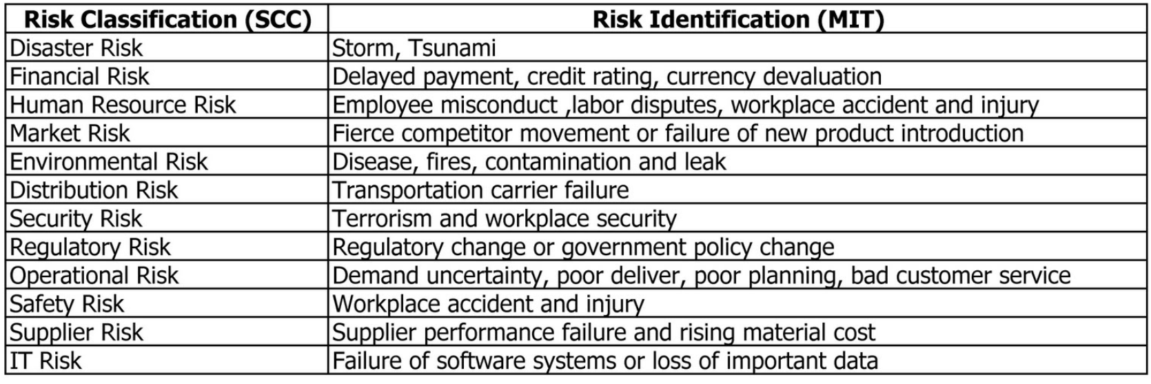
Figure 3: Common Risk Areas
Backup
Backup works with the Risk Management team and other teams to forecast, analyze and mitigate specific threat vectors for targeted divisions in the organization and to restore essential people, processes, technologies and supply chains for stabilizing the organization in the event of a disaster. They work with various teams to have an actionable business and operational capability. The following diagram depicts a typical backup lifecycle.

Figure 4: Backup Lifecycle
Some common outputs an IT Disaster Recovery professional should be familiar with include:
- Backup Policy and Charter - Most organizations will have a policy stating the strategy and executive support in the times of disaster.
- Risk Assessments – These identify and analyze potential risks and threats to the overall organization's performance before a disaster event is realized.
- Business Impact Analysis - This determines the impact of specific disasters on specific operational functions. This is commonly defined as systematic, repeatable and substantially defensible analysis to identify, measure, and validate potential impacts an interruption would cause to a business process.
- Continuity Requirements – This determines specific continuity performance metrics for specific supply chains, systems and processes including desired recovery time objectives and recovery point objectives.
Disaster Recovery Plans
Disaster Recovery Plans are a component of backup that focuses on mitigating the impact of forecasted disasters on specific targeted systems and processes. For un-forecasted disasters where no predefined recovery plan is available, the disaster recovery plan covers the roles and responsibilities for handling the disaster.
Emergency Management (Business Response) Teams
Emergency Management Teams manage the complexity of a disaster event providing situational awareness, impact analysis and triaging mission teams to recover the organization as fast as possible. They are uniquely trained for high stress situations and have the ability and authority to make decisions quickly to restore the organization. Typically, these response teams utilize the Incident Command System (ICS) to recover the organization as fast as possible.
Backup Standards
While there is a significant set of regulations and laws pertaining to the continuity and resiliency for governments and publicly traded companies in different countries, there is also a growing list of accepted international standards from the International Organization for Standardization (ISO): ISO 22301 (standard) and ISO 22313 (implementation). Note that ISO 22301 and 22313 should be viewed as a minimum bar and not a final goal of organization.
Even if an organization passes an ISO 22301 audit, doesn't mean they have an effective backup or disaster recovery capability.
Other common standards and regulations which cover backup and disaster recovery include:
| Standard | Purpose | |
| ISO 9001 | Quality requirements | |
| ISO 14001 | Environmental management systems - Requirements with guidance for use | |
| ISO 19011 | Guidelines for auditing management systems | |
| ISO/IEC 20000-1 | Service Management | |
| ISO 22300 | Societal security – Terminology | |
| ISO/PAS 22399 | Societal security - Guideline for incident preparedness and operational continuity management | |
| ISO/IEC 24762 | Information technology — Security techniques and guidelines for Information and communications technology disaster recovery services | |
| ISO/IEC 27001 | Information Security Management Systems | |
| ISO/IEC 27031 | Information technology — Security techniques — Guidelines for information and communication technology readiness for backup | |
| ISO 31000 | Risk Management — Principles and Guidelines | |
| ISO/IEC 31010 | Risk management — Risk assessment techniques | |
| ISO/IEC Guide 73 | Risk management — Vocabulary | |
| BS 25999-1 | Business continuity management — Code of practice, British Standards Institution (BSI) | |
| BS 25999-2 | Business continuity management — Specification, British Standards Institution (BSI) | |
| SI 24001 | Security and continuity management systems — Requirements and guidance for use, Standards Institution of Israel | |
| NFPA 1600 | Standard on disaster/emergency management and backup programs, National Fire Protection Association (USA) | |
| Backup Plan Drafting Guideline | Ministry of Economy, Trade and Industry (Japan), 2005 | |
| Backup Guideline | Central Disaster Management Council, Cabinet Office, Government of Japan, 2005 | |
| ANSI/ASIS SPC.1 | Organizational Resilience: Security, Preparedness, and Continuity Managements Systems – Requirements with Guidance for UseSS 540: 2008, Singapore Standard for Backup Management | |
| ANSI/ASIS/BSI BCM.01 | Backup Management Systems: Requirements with Guidance for Use | |
Positioning Disaster Recovery
There are five phases to disaster response, Watch, Mobilize, Assess, Stabilize and Close. These phases cover the broad range of activities that typically need to be addressed in a disaster event, in order, and are illustrated in the diagram below:
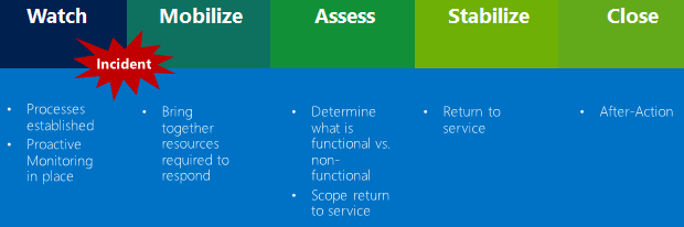
Figure 5: Standard Disaster Response Protocol
When starting a DR oriented project, it's crucial to utilize the organization's Business Impact Assessment (BIA) and Risk Assessment (RA) to define needs in responding to a disaster. These needs will help the organization define their disaster response strategy from an IT perspective. Often times the IT organization will have the RA/BIA and Continuity requirements (CR) documented or will know crucial business services and the corresponding dependent IT systems. It is important that the disaster recovery plan align to the RA/BIA as well as Continuity Requirements (CR) of the organization. The DR plan should be tightly scoped to the targeted services and supply chains as well as forecast the impact on adjacent dependent IT assets and processes.
It is important to note that the IT organization must always own its own RA, BIA and CR. While a DISASTER RECOVERY project can present options, observations, the engagement cannot represent itself as owning the final strategy or guaranteeing risk scenarios to the customer (board of directors, shareholders, or political leaders). It's generally regarded as a bad practice for customers to delegate their backup strategic decisions to a third party. Promoting a disaster recovery plan without regard to the customer's backup requirements, customer's emergency implementation capability or the critical dependences (people, processes and IT systems) is generally regarded to be an irresponsible action.
Plan-Do-Check-Act (PDCA) Model
Typically, organizations will utilize a variation of the Plan-Do-Check-Act (PDCA) model to drive their backup and disaster recovery strategy to reality. Not only is it an ISO 22301 standard, the PDCA model promotes disaster recovery as a perpetual commitment of implementation including processes, technology, organizational "muscle memory" and executive commitment. This is not a product or technology, it is a process-based effort.
An example of the PDCA is provided below:

Figure 6: Plan-Do-Check-Act (PCDA) Model
PDCA is an essential top-down approach to help make sure backup strategies are aligned with executive needs of the organizations. However, it must be complimented with a bottoms-up capability perspective to ensure that the strategy can be implemented by the disaster response team. When DR plans are designed from the top down without regard to the response capabilities of the organization, the ability to run under pressure with limited staff in a disaster is often compromised. Often, the tools, training and muscle memory of the teams will determine if the organization effectively recovers with the disaster recovery plan.
Recovery Concepts Overview
RTO/RPO
From a technology perspective, Recovery Point Objective (RPO) and Recovery Time Objective (RTO) are important in the guidance to set-up your disaster recovery plan. These metrics are usually documented by the backup team in the Continuity Requirements for specific business functions.
The Recovery Point Objective (RPO) covers the maximum amount (in time) of data that can be lost in case of a disruption. It answers the question, "to what point in time can I recover?"
The Recovery Time Objective (RTO) covers the maximum amount of time it will take from the disruption to bring back the business functions including data. It answers the question, "at what point in time can I expect business operations to continue?"
The RPO and RTO figures we find most in the SLA are focused on the regular back-up and recovery processes. As part of Disaster Recovery (DR) the RPO and RTO figures normally would be higher. Based on the Backup (BC) plan realistic values need to be set. As seen in the figure below ideally RPO and RTO are business driven numbers, that rollup from the RPO and RTO for the technical components that make up the business application.

Figure 7: RPO/RTO
SIPOC
Most backup teams look at the organization as a whole and work on a resiliency strategy that incorporates restoring the specific business operation as a whole. The SIPOC acronym (a Six Sigma methodology) stands for supplier, inputs, processes, outputs, and customers. This model is often used to assist groups in understanding the interrelationships of their processes and how work is currently performed within each process. An example of this is provided in the following diagram:

Figure 8: SIPOC Example
Dependency Categories
There is a common terminology used when outlining business dependencies (non-IT assets) during DR analysis. It is critical to understand how technology can impact each of the areas listed below and familiarity with these terms helps with DR planning to address the needs of the organization's business. These terms include, but are not limited to:
- A Supplier is any person, entity or organization that provides inputs to the current process. A supplier can provide information, data, documents, guidelines, transactions, supplies, equipment or raw material. An internal supplier is internal to the organization, such as a team or business group, and provides inputs for the process in question. An external supplier is an external entity or organization providing inputs to the process.
- An Input is anything which feeds into the process as a document, guidelines, product, data, transaction, specialized equipment or raw material.
- Workforce, for the purpose of the Dependency Analysis, is any employee or non-payroll worker. These would include vendors and independent contractors.
- A Location is a place where something is or could be located; a site, such as a specific building name or number.
- An Application refers to a computer program or group of programs designed for end users. Applications are self-contained programs that perform a well-defined set of tasks under user control.
- A Vendor is a business entity contracted to provide a service or infrastructure element to customers or clients. Vendors can be any third-party provider, regardless of the service they provide.
- Data and Vital Records refer to any data or information required to perform your process. Data and vital records can be electronic or hard copy and reside in a number of different formats or locations.
- Specialized Equipment is any specialized equipment, machine or tool required to perform your process. Your list of equipment and tools should not include normal office equipment and supplies such as laptops, PCs, printers, copiers, fax machines, paper, pens and general desk supplies.
- A Partnership is a formal contractual relationship established to provide regular business services between two companies.
- An Output is anything that was created by the process such as a document, transaction, product, data or information and given to a customer of the process. An output of your process can be an input of another related process. Example: "Customer Balance" can be an input to a "Collections Process". An output can be given to an internal customer, external customer, or a related process.
- A Customer is any team, business unit or organization that receives a product or service from your process. Internal customers are colleagues, departments or groups inside the organization who receive products, services, support, or information from your process. External customers are individuals or organizations outside of the organization who are usually associated with paying money for our products and services, or are an extension of your process under a contractual relationship.
Technical Dependency Analysis (TDA)
About thirty years ago, most organizational IT solutions were in massive self-contained propriety systems of completion. Today, almost all solutions have other applications, networks and data which serve as dependencies for their uninterrupted operation. This means DR teams have to understand the dependencies and relationships the targeted solutions has with other systems.
Technical Dependency Analysis (TDA) is a process to define all technology and processes components as well as key personnel to keep a specific IT capability operational. Common TDA questions asked by the Backup Team for each critical system include:
| Responsible for Data | Data Elements |
| Business Unit Lead |
|
| Application & Infrastructure Support Team |
|
The Technical Dependency Analysis (TDA) examines the application(s) and supporting infrastructure that a process depends on to determine, at a minimum, the following:
- Recovery Time Capability (RTC);
- Recovery Time Estimate (RTE), if they haven't been tested ;
- Recovery Point Capability (RPC) ;
- Recovery Point Estimate (RPE), if they haven't been tested
The data collected from this analysis will be used to identify gaps between the business process recovery requirements and the recovery capabilities of the applications and supporting infrastructure.
- Recovery Time Capability means the technical dependency has been proven through a test and may or may not meet the RTO requirement.
- Recovery Time Estimate means the technical dependency has not been proven through a test and the RTC has not been validated.
- Recovery Point Capability means the technical dependency has been proven through a test and may or may not meet the RPO requirement.
- Recovery Point Estimate means the technical dependency has not been proven through a test and the RPC has not been validated.
Performing the due diligence of TDA will lead towards the development of service dependency maps, which outline the dependent systems and services for each application providing capability to an organization's specific business functions.
Disaster Recovery Planning Approach
To optimize your backup plan to support your IT Disaster Recovery strategy, multiple workshops are necessary:
- Kick-off and positioning: Provides all attendees of the program detailed information on the goals, planning and their roles, next to a common language when talking about disaster recovery.
- Service Mapping: Collects all information about the business function or service, its components, the parties involved and the different agreements. Insights gathered in this session are essential in planning for the recovery from a disaster.
- Scenario identification: Identifying all possible DR scenarios and ranking those on probability, impact and mitigations already in place. Information from this session is used to validate the coverage of the technical recovery scenarios and evaluate if the information from the Business Impact Assessment is complete. Based on the identified scenarios, the response and the corresponding processes are designed.
- Information Needs and War room Facilities: Based on the identified recovery scenarios and their constraints, information needs and facility requirements are identified (email not available, no phone, no access to the office, etc.). This area is operated by the Response Leadership Team. It will be crucial to design a strategy that the response can easily run. Too much complexity and manual processes is the root of most Response failures.
- Responsibility and accountability: Based on the prior workshops a RACI matrix will be set up for extending / maintaining the DRP and running a Disaster Recovery. Further Critical Success Factors (CSF) and Key Performance Indicators (KPI) will be set up to measure and extend the DR.
While the information gathered and documented is valuable, it is also quite volatile. Embedding disaster recovery in the change process will allow the organization update the DR information as part of changes that are implemented. It is a good practice to assign an owner to the information and set relevant review intervals to verify that the information is up-to date.
Emergency Response (The Incident Command System)
It's a sad fact that most disaster recovery plans are failures. There are a variety of reasons for this:
- Too much complexity
- Too much specialized human involvement
- Decisions by consensus
- Lack of testing (this brings out the missing details)
- Lack of real world disaster management experience by the planning team
Needless to say, when a real disaster hits, it's the emergency response team that will mobilize with the executive leadership team to stabilize the organization, its people, process, partners and customers in their time of need.
Often DR plans ignore the implementation capabilities of the emergency team and assume the organization will have access to their most talented technical team to fix or restore critical systems. To use a practical example, the best Active Directory administrative team will effectively restore the Active Directory service for the company after a disaster has occurred. IT leadership often assumes the incident response team that addresses common outages can manage a major disaster. These assumptions are often ill founded in a real disaster. As a guideline, it is safe to assume an IT organization will have access to 50% of their employees operating at 50% mental capacity under stress. As a general practice, DR plans should incorporate this assumption in the recovery capabilities of the organization.
For a variety of reasons, often regular organizational bureaucracy is ill equipped to handle the pressure and rapid pace massive disaster management requires. Emergency Response requires a clear command model with focused teams to quickly rebuild the organization's systems and services effectively. While there are variety of approaches, most successful Emergency Response teams utilize a variation of the Incident Command System (ICS). ICS is an internationally recognized operational command and control model to mobilize, access and triage the crisis and incorporate and responsibly orchestrate all available talent available while working with critical partners, government organizations and key stakeholders. ICS as a process has been maturing and proving itself for decades. The reason why organizations use ICS: it consistently works.
An example of IT Incident Command Systems (ICS) model for Disaster Management is provided in the diagram below:
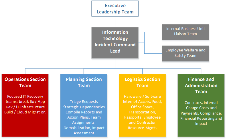
Figure 9: Incident Command Structure Example
These technology response teams will support the Operations Lead on target missions to support restoring key organization functions and supply chains. The Operations Lead directs all response/tactical actions. For government organizations, the Operations will lead a variety of responsibilities working with other ICS leadership.
Typical IT restoration will consist of multiple teams in a separate IT Recovery Team or injected into a task force unit. Needs assessments will be triaged to focus on the most important systems first. IT restoration encompasses two types of missions:
- Break/Fix missions: Repair and restore of existing IT assets
- Examples include restoring an existing application or service from backup.
- Examples include restoring an existing application or service from backup.
- Complex missions: Major rebuild of key IT assets.
- Examples include setting up new emergency cloud services, rapidly building applications or addressing significant cyber-attacks while in crisis.
- Examples include setting up new emergency cloud services, rapidly building applications or addressing significant cyber-attacks while in crisis.
It will be important for the DR strategy be automated and standardized as much as possible to help these teams be successful. Often, the IT Recovery Team is managing hundreds of separate uncoordinated DR missions in a major disaster. As a recommended practice, when evaluating the technical dependencies of an organization, examine the organization's incident response capabilities carefully to help make sure they can complete the DR plan developed.
Microsoft Cloud-Based Disaster Recovery Capabilities
Planning Backup & Disaster Recovery for Cloud Environments
Cloud workloads fall into two categories – stateful and stateless. Stateful workloads rely on the infrastructure to provide availability and therefore not have the constructs within the application or service to manage their own state in a cloud environment. In cloud architectures, stateful resource pools provide virtual machine resiliency through availability constructs such as virtual machine Live Migration. Stateless workloads rely on the application or service to provide availability and contain the constructs within the service to continue service during outages. In some cases, these workloads provide resiliency at the cost of operating during failures with diminished capacity.
Cloud infrastructures provide availability constructs such as upgrade domains which define boundaries of failure. These boundaries differ based on public or private cloud offerings and each model's capabilities are outlined in the sections below.
On-Premises Cloud DR Capabilities
For private cloud architectures, availability and upgrade domains are defined by discrete resource pools which can support a level of availability within or between one another using technologies such as virtual machine mobility, replication and backup.
Virtual Machine Mobility
Virtual machine mobility for on-premises infrastructures running Windows Server 2012 R2 Hyper-V is supported by two technologies: Hyper-V Live Migration and Hyper-V Storage Migration.
Hyper-V Live Migration
makes it possible to move running virtual machines from one physical host to another with no effect on the availability of virtual machines to the services running within it.
Hyper-V Live Migration is divided into two categories:
- Shared Storage-based live migration. In this instance, the hard disk of each virtual machine is stored on either a local CSV or a central SMB file share and live migration occurs over either TCP/IP or the SMB transport. You then perform a live migration of the virtual machines from one server to another while their storage remains on the central local CSV or SMB share.
- "Shared-nothing" live migration. In this case, the live migration of a virtual machine from one non-clustered Hyper-V host to another begins when the hard drive storage of the virtual machine is mirrored to the destination server over the network. Then you perform the live migration of the virtual machine to the destination server while it continues to run and provide network services.
Windows Server 2012 R2 also supports Live storage migration, which supports the movement of virtual hard disks that are attached to a virtual machine that is running. This provides the flexibility to manage storage without affecting the availability of virtual machine workloads, perform maintenance on storage subsystems, upgrade storage-appliance firmware and software, and balance loads while the virtual machine is in use. Live storage migration is supported for virtual hard disks on shared and non-shared storage subsystems (when using Hyper-V over SMB designs).
Virtual Machine Replication
Virtual machine replication for on-premises infrastructures is supported by the Windows Server 2012 R2 Hyper-V Replica feature. Hyper-V Replica provides a workload agnostic failure recovery solution by providing asynchronous replication of virtual machines over standard network protocols (HTTP or HTTPS) from one Hyper-V host or cluster to another remote Hyper-V host or cluster without relying on storage arrays or other software replication technologies. Windows Server 2012 R2 Hyper-V Replica supports replication between source and target Hyper-V servers (or clusters) which can be physically co-located or geographically separated. It can further support extending replication from the target server to a third server through the extended replication feature. Hyper-V Replica tracks the write operations on the primary virtual machine and replicates these changes to the replica server in configurable frequencies of 15 minutes, 5 minutes or 30 seconds and additional recovery points can be configured to be stored for 24 hours. Hyper-V Replica also supports both planned and unplanned failover scenarios with advanced logic such as TCP/IP re-addressing of the host as part of the failover process.
Virtual Machine Backup
Virtual machine backup for on-premises infrastructures is provided through backup software which supports the Hyper-V Volume Shadow Copy Services (VSS) Writer. The ability to back up open files is required to provide backup and VSS creates frozen copies of open files, helping to make sure that virtual machines do not have to be put into hibernation or be shut down before a consistent backup can be made. In a virtualized data center, there are three commonly used backup types: host-based, guest-based, and a SAN-based snapshot. The following table contrasts these types.
| Backup Capability | Host-Based | Guest-Based | SAN Snapshot |
| Protection of virtual machine configuration | × | × | |
| Protection of host and cluster configuration | × | × | |
| Protection of virtualization-specific data | × | × | |
| Protection of data inside the virtual machine | × | × | × |
| Protection of data inside the virtual machine stored on pass-through disks, iSCSI and vFC LUNs and Shared VHDx'es. | × | × | |
| Support for Microsoft Volume Shadow Services (VSS)-based backups for supported operating systems and applications | × | × | × |
| Support for continuous data protection | × | × | × |
| Ability to granularly recover specific files or applications inside the virtual machine | × | × | × |
Note that the use of SAN volume snapshots is highly dependent on the storage vendor's level of VSS and Hyper-V integration. SAN volume snapshots are typically block-level, and they only utilize storage capacity as blocks change on the originating volume.
System Center 2012 R2 Data Protection Manager allows disk-based and tape-based data protection and recovery for Hyper-V servers. Data Protection Manager supports the protection of standalone or clustered computers running Hyper-V in failover clusters using shared (cluster shared volumes) or SMB storage.
Azure Site Recovery (ASR) On-Premises DR for physical instances including MSCS clusters, virtual instances running on VMWare and Pre-2012 Hyper-V is available using ASR. ASR enables your organization to meet stringent disaster recovery needs, eliminate the impact of local backups, and manage application uptime to meet high availability requirements. ASR uses advanced technologies like Continuous Data Protection (CDP), Asynchronous Replication over IP, Application Failover/Failback, and WAN Optimization for disaster recovery of data.
CDP technology enables ASR to capture data for recovery purposes and lets you decide upon any recovery point in time to recover your lost/corrupted data.
Asynchronous replication, configurable in 1-to-1, 1-to-N, and N-to-1 configurations support short or long distance DR requirements over IP networks, while WAN optimization technologies allow ASR to support even large applications using minimal bandwidth. Instead of the shared- disk model that conventional high availability clustering software uses, ASR Application failover/failback leverages a shared-nothing model. All these capabilities are combined into a single software-based platform that supports Windows, Linux, and UNIX environments as well as heterogeneous storage architectures (DAS, SAN, NAS, iSCSI, FC). A key differentiator for ASR is that it provides DR solutions that enable recoveries from or at remote sites within minutes through an efficient use of available bandwidth. This debunks the perception that DR configurations are expensive and inflexible, allowing customers to preserve their existing investments in hardware, software, and networks as they deploy a DR solution that can meet stringent recovery point objective, recovery time objective, and recovery reliability requirements.
Hybrid Cloud DR Capabilities
Public cloud architectures support a wide range of availability for workloads running within their service. While public cloud offerings still ultimately reside on physical hardware running in physical datacenters across the world, this is where the similarity ends. Public cloud offerings differ vastly from that of private cloud environments as they are exposed as services, which means that traditional constructs organizations expect from what may look like a familiar capability (such as virtual machines) ultimately is using a different set of constructs for the consumer based solely on what the provider chooses to expose. Furthermore, new constructs are often developed by the provider to support a greater degree of service separation and availability for consumer workloads. These services are often backed by a Service Level Agreement (SLA) and the granularity often is exposed at the service level. Azure's SLAs are available publicly and are aligned directly to each of the services being provided through its management portal.
A key consideration when deploying workloads to hybrid cloud environments is that the organization is mixing availability constructs between what they provide internally through on-premises cloud infrastructures and what the public cloud provider has exposed through various service offerings. This mixing of constructs means that DR planning of a workload which spans public and private cloud infrastructures must consider both the capabilities and SLAs provided by both environments to assess availability and recovery needs.
Azure provides a wide range of capabilities which support the availability of workloads spanning on-premises and public cloud IaaS-based solutions. These capabilities change rapidly with each new release and an overview of currently available IaaS services is provided below.
First, availability of workloads hosted in Azure virtual machines is achieved by using multiple virtual machines for continuity. This provides general availability of the workload during local network failures, local disk-hardware failures, and any planned downtime that the platform might require. Availability of a workload comprised of multiple virtual machines is achieved by adding them to an availability set. Availability sets are directly related to fault domains and update domains in cloud infrastructures. A fault domain in Azure is defined by avoiding single points of failure, like the network switch or power unit of a rack of servers. When multiple virtual machines are connected together in a cloud service, an availability set can be used to help ensure that the virtual machines are located in different fault domains. The following diagram shows two availability sets, each of which contains two virtual machines.
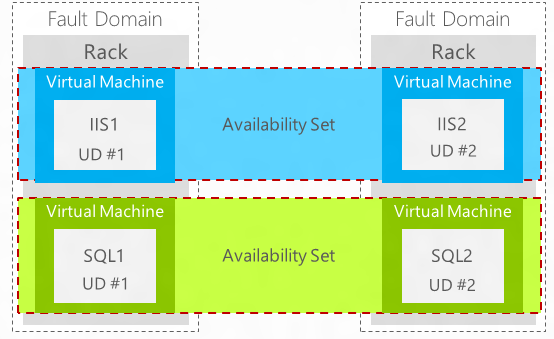
Figure 10: Azure Availability Sets
Azure periodically updates the underlying infrastructure that hosts the instances of running workloads and during that process a virtual machine is shut down when an update is applied. An update domain is used to help make sure that not all of the virtual machine instances are updated at the same time. When you assign multiple virtual machines to an availability set, Azure helps to make sure that the virtual machines are assigned to different update domains. As discussed previously, the Windows Azure virtual machine availability concepts are not the same as on-premises Hyper-V. To support high availability for workloads hosted in Azure, multiple virtual machines per application or role must be created, and Azure constructs such as availability groups and load balancing must be utilized. Additional information about these constructs can be found in the Infrastructure-as-a-Service Product Line Architecture Fabric Architecture Guide.
VMWare and Physical Environments
The Azure Site Recovery Service contributes to your backup and disaster recovery (BCDR) strategy by orchestrating replication, failover and recovery of virtual machines and physical servers. Machines can be replicated to Azure, or to a secondary on-premises datacenter.
Azure Site Recovery Service is a hybrid cloud service which coordinates and manages the protection of VMWare virtual machines located in private cloud infrastructures managed by VMWare ESX servers. Azure Site Recovery Service orchestrates failover of these virtual machines from one on-premises ESX host or cluster to another on-premises ESX host or cluster located in secondary location.
Azure Site Recovery Service uses the concept of "vaults" in Azure to store configuration data related to the protection of single and multi-tier workloads which are defined as Recovery Plans. See the following configuration example.

Recovery Plans are linear orchestration plans which allow for the grouping of virtual machines into one or more failover groups. Recovery plans also allow for the addition of manual steps and the insertion of automation (scripts) which can be run as part of a failover event. When combined together, Recovery Plans support many of the requirements for failover multi-tier application of workloads that span multiple virtual machines. While there are many technologies available which provide protection of virtual machines themselves, very few recovery solutions exist which provide the fabric management infrastructure with the intelligence to see multiple virtual machines as composed applications and services with differing failover needs and actions for each tier.
Azure Site Recovery Service additionally automates planned and unplanned failover activities across sites and supports the TCP/IP readdressing needs when failover is performed across separate network segments. Finally, recovery plans can be tested in isolation without disruption to the running workload, supporting activities such organizational DR drills and plan verification.
How Does ASR Protect On-Premises Resources?
Site Recovery helps protect your on-premises resources by orchestrating, simplifying replication, failover and failback in a number of deployment scenarios. If you want to protect your on-premises VMware virtual machines or Windows or Linux physical servers, here's how Site Recovery can help:
- Allows VMware users to replicate virtual machines to Azure.
- Allows the replication of physical on-premises servers to Azure.
- Provides a single location to setup and manage replication, failover, and recovery.
- Provides easy failover from your on-premises infrastructure to Azure, and failback (restore) from Azure to on-premises.
- Implements recovery plans for easy failover of workloads that are tiered over multiple machines.
- Provides multi VM consistency so that virtual machines and physical servers running specific workloads can be recovered together to a consistent data point.
- Supports data replication over the Internet, over a site-to-site VPN connection, or over Azure ExpressRoute.
- Provides automated discovery of VMware virtual machines.
What is Needed to Configure ASR for VMware
| FEATURE REFERENCE | |
| Set up protection between on-premises VMware virtual machines or physical servers and Azure | https://azure.microsoft.com/en-us/documentation/articles/site-recovery-vmware-to-azure |
| Site Recovery Overview | https://azure.microsoft.com/en-us/documentation/articles/site-recovery-overview/ |
| Site Recovery components | https://azure.microsoft.com/en-us/documentation/articles/site-recovery-components/ |
Native Application Platform Considerations
As stated earlier, all cloud solutions should be built with the workload in mind. From a DR perspective, any cloud solution should respect the availability constructs provided by the workload itself. While Hyper-V and Azure support virtual machine availability through some of the constructs outlined above, many workloads provide native capabilities to support service availability within their application or service. Examples of this include Microsoft SQL Server Always-On Availability Groups, Active Directory Domain Services (AD DS) domain controllers, Exchange Server Database Availability Groups (DAG) and Lync services. In some cases, it is either not supported or recommended to combine the availability constructs of the cloud with those of the workload. In these cases, it is often preferable (or required) to allow the workload to manage its own availability. Some workload availability constructs can be combined with cloud capabilities to further enhance their availability. Examples of this include SQL Server Always-On Availability Groups support in Azure and enhancements to AD DS support in virtualized environments. As outlined in the DR concepts, it is important to include workload availability constructs as Recovery Point Capabilities when determining RTO/RPO for cloud-based solutions.
Summary
Backup and Disaster Recovery planning is a required element of any cloud-based workload deployment and therefore is a core functional area of the Cloud Platform Integration Framework (CPIF). This document is meant to serve as a framework for applying DR concepts in workload planning and design for public, private and hybrid cloud environments. These concepts and capabilities can be applied to various applications and services and therefore require analysis of each workload's capabilities and support for the constructs discussed earlier. Along with this guide, a series of workload-specific scenario guides are available to outline practical application by various workloads for the framework outlined in this document.